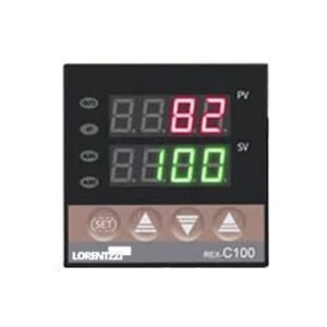
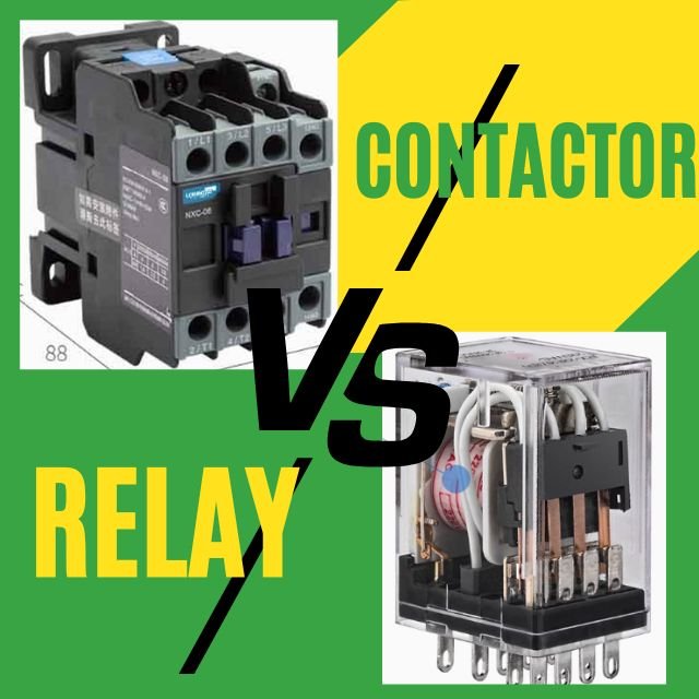
In temperature control systems, PID temperature controllers play a very important role. Whether you are an engineer, technician, or DIY enthusiast, mastering the wiring skills of PID temperature controllers can make your temperature system design work smoother. In this guide, we will walk you through the steps of wiring a PID controller to ensure your system setup is successful.
Understanding The PID Temperature Controllers
PID temperature controllers can not only be used to help you reach and maintain the desired temperature, but can also be used as a temperature indicator to display the temperature, or as a temperature relay to perform certain actions once the temperature reaches an alarm value.
The PID temperature controller is one of the PID controllers that is mostly used to regulate temperature, PID controllers can be utilized in various fields as well, such as maintaining pressure and even balancing drones etc.
A PID controller is a control loop feedback mechanism (controller) that continuously calculates an error value as the difference between the desired set point (SP) and the measured process variable (PV) and applies corrections based on Proportional, Integral and Derivative terms, hence the name PID. This ensures that the final control element keeps the process at the set point.
Gathering Necessary Materials
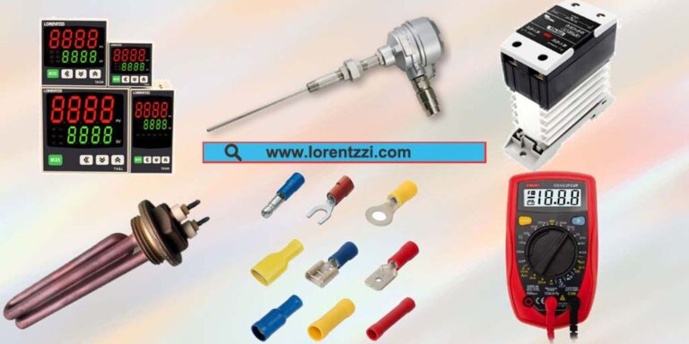
Before you begin, ensure you have the following materials:
- One PID temperature controller.
- One temperature sensor (thermistor, RTD, or thermocouple).
- An actuator, such as a solid state relay or AC contactor.
- A Final control element (heater, cooler, or valve).
- Some wires and connectors.
- One screwdriver and some wire strippers.
- A Multimeter for testing.
Safety Precautions

Before operating the PID temperature controller wiring,please note the following 3 points:
- Turn off power before making any connections.
- Use insulated tools and wear protective gear.
- Work in a well-ventilated area to avoid overheating.
Wiring the PID Controller
Step 1: Connect The Power Supply
The first step is to power the PID temperature controller, please make sure the input voltage is correct, because the input voltage can be a single working voltage, such as 110VAC, 220VAC, 24VDC, 12VDC, etc., or a wide voltage range, such as 90-265VAC.
If the input voltage is DC voltage, please make sure the positive and negative poles are connected correctly. If there is no reverse polarity protection circuit inside, the reverse polarity will damage the PID temperature controller.
Note: Do not turn on the temperature controller power before completing the following 3 steps.
Step 2: Connect The Temperature Sensor
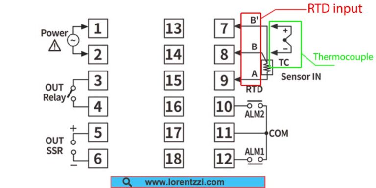
Next, connect the temperature sensor to the controller. This usually involves two or three wires, depending on the type of temperature sensor. For example, a thermocouple will have two wires(the positive pole is red, the negative terminal is with blue cable), while a Resistance Temperature Detector (RTD) will have three or four(simply called ABB, A is positive terminal with red color, B is negative terminal with blue cable). Want to know more differences between the thermocouple and RTD, see our article: What Are Differences Between Thermocouples And RTDs?
Step 3: Connect Output To Actuator For Final Control Element
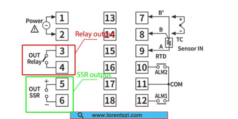
Most PID temperature controllers have two outputs, relay and SSR, and you can choose the output you want by changing the program according to the user manual.
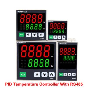
The output of Lorentzzi PID temperature controller can not only be SSR and relay output, we can also provide analog output, such as 4-20mA or 0-5VDC, making the control temperature more precise. Additionally, PID temperature controller with RS485 remote control is available.
First determine which actuator you want to use to control the heating element. Generally speaking, solid-state relays are most commonly used in temperature control systems because of their fast switching time. Then change the output to SSR according to the user manual, and finally connect the positive and negative poles of the SSR to the positive and negative poles of the PID thermostat SSR output respectively.
Another situation is if you want to use relay output to run the heater, in this case, external AC or DC power should be passed through this output contact, you can use DC control AC or AC control AC SSR or AC contactor as actuator to control the heating element.
Step 4: Evaluate Alarm Function Is Necessary Or Not
The alarm function is also very important in the temperature control system, it can help avoid serious accidents such as over-temperature. Usually, the alarm output of the PID temperature controller is a SPST NO contact, if the heater temperature is higher than the alarm value you set, the alarm relay will become NO to NC, so if you add an alarm horn to it, the alarm horn will turn on, so that you can get this over-temperature information.
Same as the relay output, an external AC power should be provided to this contact to run an alarm horn.
Step 5: Testing and Calibration
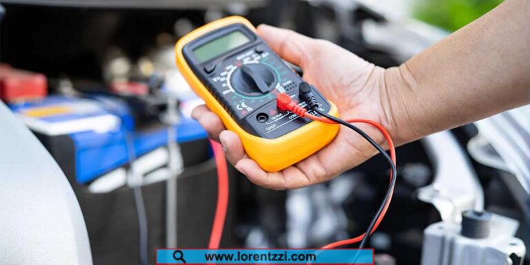
Once everything is connected, power up the system and check for proper operation. The PID controller should display the current temperature and respond to changes.
If the display does not indicate correctly but shows an error code, please check whether the temperature sensor is damaged. In our digital TCN4 series PID temperature controller, if the temperature sensor is damaged, it will intelligently display an “open circuit” error code, so you can easily know where the problem is
Maintenance and Long-Term Care
Regularly inspect the wiring for signs of wear or damage. Clean and tighten connections as needed. Keep the controller’s display and buttons clean and free of debris.
Conclusion
PID temperature controller wiring is very simple for an engineer or electrician if following the steps written by us.
If you have any questions about our PID temperature controller, please feel free to contact us at shonxu@lorentzzi.com. Lorentzzi is a PID temperature controller manufacturer in China, we supply various kinds of PID temperature controllers with the best quality and affordable price.

