Contents
Overview
Although there are many models and specifications of solid state relays on the market, the working principles of solid state relays are basically similar. It is mainly composed of three parts: input (control) circuit, drive circuit and output (load) circuit. The working principle of the solid state relay is illustrated below through two working principle diagrams of the solid state relay.
Schematic diagram 1 of solid state relay
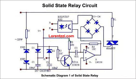
The truncated sinusoidal signals taken from DW1 and DW2 output square waves through inverter BG1, and then output peak pulse signals through operational amplifier A. Spike pulses are added between the AC diagonal lines of D3~D6 and the control pole and cathode of the SCR, and the DC diagonal lines of D3~D6 are connected to the output end of the photocoupler. When a low-voltage and small-current signal is input from A and B, the diode emits light and the photosensitive tube is turned on, so the peak pulse output from the A operational amplifier triggers the SCR to turn on, and the angular load RL is energized. When there is no signal input from A and B, the photocoupler BG2 is cut off, and the peak pulse cannot pass through, so that the SCR cannot be turned on.
Schematic diagram 2 of solid state relay:

When there is no input signal, the phototransistor in GD is cut off, and VT1 is an AC voltage zero-point detector, which obtains base current through R3 and conducts in saturation, clamps the gate of VTH at a low potential and is in an off state. When there is an input signal, the phototransistor is turned on, and the state of VTH is determined by VT1 at this time. When the power supply voltage is greater than the zero-crossing voltage, the voltage of the voltage dividing point P of the voltage divider R3 and R2 is greater than VBE1, and VT1 is saturated and turned on. The gate of the SCR is closed because it is clamped at a low potential, and the gate of the TR is in an off state because there is no trigger pulse. Only when the power supply voltage is lower than the zero-crossing voltage and the voltage at point P is lower than VBE1, G1 will be cut off, and the SCR gate will be turned on by receiving the trigger signal. When the trigger pulse is obtained at the gate of TR, TR is turned on. Thereby turning on the load power.
Conclusion
Here above are two working principles for the solid state relay, generally, solid state relays have been widely used in computer peripheral interface devices, electric furnace heating constant temperature systems, numerical control machinery, remote control systems, industrial automation devices; signal lights, scintillators, lighting stage lighting control systems; instrumentation, medical equipment, copiers, automatic washing machines; automatic Fire protection, security systems, and switching switches for power capacitors used as grid power factor compensation, etc. In addition, solid-state relays are widely used in chemical, coal mines and other occasions that require explosion-proof, moisture-proof, and corrosion resistance.
Solid state relays have good moisture-proof, mildew-proof and anti-corrosion properties, and are also excellent in explosion-proof and ozone pollution prevention. Solid-state relays also have low input power, high sensitivity, low control power, good electromagnetic compatibility, low noise and low operating frequency. advanced features.