
Because most proximity sensors operate at 6-36V DC voltage, therefore, when you are using a proximity sensor, a reliable and stable 12V or 24V DC power source, such as Switched-Mode Power Supply(SMPS), is required.
The SMPS can convert commonly used AC power to DC power, then provide the stable power to the proximity switches.
However, do you know how to wire a proximity sensor to an SMPS?
In the next section, we will provide you detailed wiring instructions, including:
- PNP sensors wiring,
- NPN sensors wiring,
- DC two-wire sensors wiring.
Definition of proximity sensor and SMPS
Proximity sensors are among the most commonly used products in industrial automation, especially the inductive proximity sensors.
We can use proximity sensors to contactlessly detect the presence or absence of objects and then perform tasks such as counting, calculating motor speed, and collision avoidance.
As for the SMPS, it is the abbreviation of Switched-Mode Power Supply, which function is to convert the AC power to DC power. You can get more information about the SMPS from our blog post: SMPS: What It Is and How It Works.
Wiring of PNP and NPN sensors with SMPS
PNP and NPN proximity sensors most commonly use three wires: brown, blue, and black.
Brown connects to the DC power supply positive, while blue connects to DC negative. When wiring to an SMPS, run the brown wire to the SMPS positive output and the blue wire to the SMPS negative output.
Nearly all proximity sensors include built‑in reverse‑polarity protection. You do not need to worry about sensor damage if power polarity is mistakenly reversed.
Four‑wire proximity sensors exist as well. They keep the same power‑supply colour convention: brown for positive and blue for negative. This means four‑wire proximity sensors use exactly the same power‑wiring setup as three‑wire models: brown to SMPS positive, blue to SMPS negative.
As for how to wire the loads for PNP and NPN sensors, you can see our blog post: PNP Vs NPN Proximity Sensors: Key Differences, Wiring Diagram And How To Choose.
Wiring of DC two-wire sensors with SMPS
Connecting a two-wire DC sensor to a switching power supply (SMPS) is the simplest method, requiring only four steps. However, to avoid short-circuiting the SMPS, it is recommended to use it in conjunction with a 24VDC coil intermediate relay.
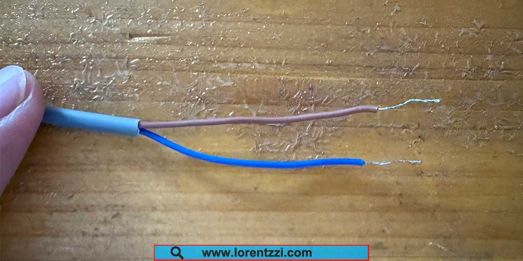
- Step 1: Determine the cable colors of the two-wire DC sensor. A two-wire DC sensor has two wires: one brown and one blue.
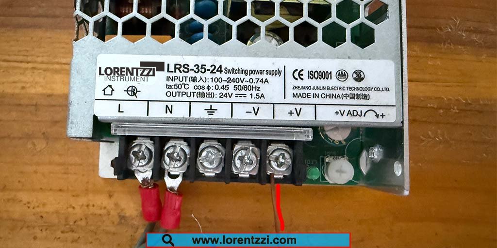
- Step 2: Connect the brown wire to the positive terminal of the SMPS.
- Step 3: Connect the blue wire to the positive terminal of the intermediate relay coil.
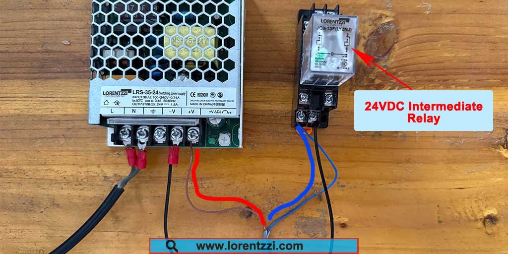
- Step 4: Connect the negative terminal of the intermediate relay coil to the negative terminal of the SMPS.
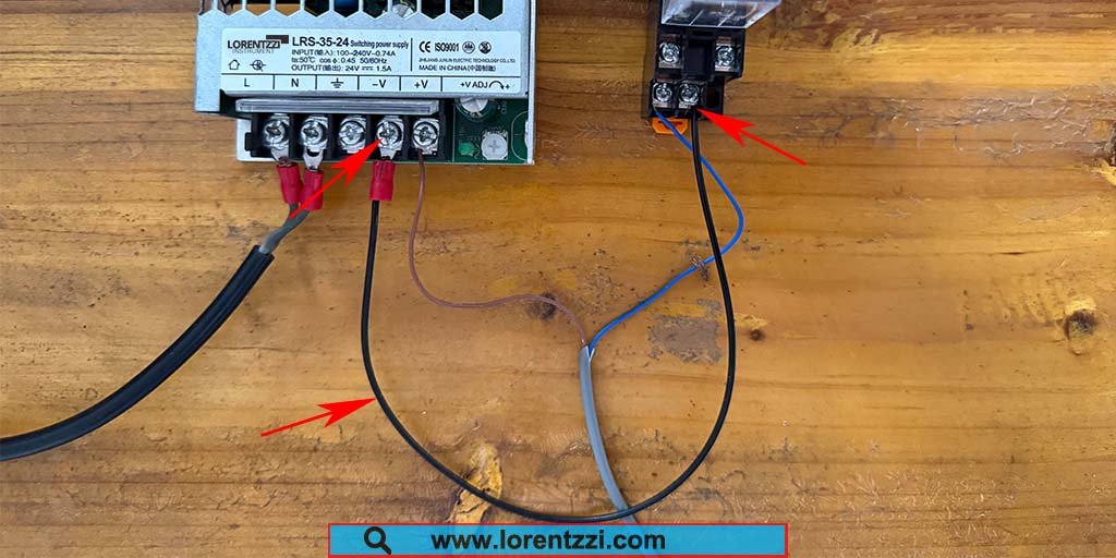
For detailed wiring instructions for the DC two-wire sensor, you can watch the following video:
Conclusion
In summary, to properly connect the proximity sensor, the brown cable should be connected to the positive terminal of the SMPS, and the blue cable should be connected to the negative terminal of the SMPS.
If you still have questions about how to connect a load or general-purpose relay to the proximity sensor signal cable, please send your questions to shonxu@lorentzzi.com, and Lorentzzi® Electric staff will reply as soon as possible.