Have you ever encountered this problem?
Your proximity sensor has been in use for a long time, its label has worn off, and it has stopped working. You want to replace it, but you’re not sure whether to choose an NPN or PNP output type.
So how can you identify whether your sensor is NPN or PNP?
This is simple for experienced technicians, but can be challenging for beginners.
Therefore, in this post, we will share 3 practical methods to determine the output type of your sensor:
- Identify from the nameplate,
- Test with a multimeter,
- Check with a dedicated sensor tester.
Let’s go through the detailed steps!
Understanding PNP NPN sensor

Before identifying whether a sensor is NPN or PNP, it is essential to understand the fundamental difference between these two output types.
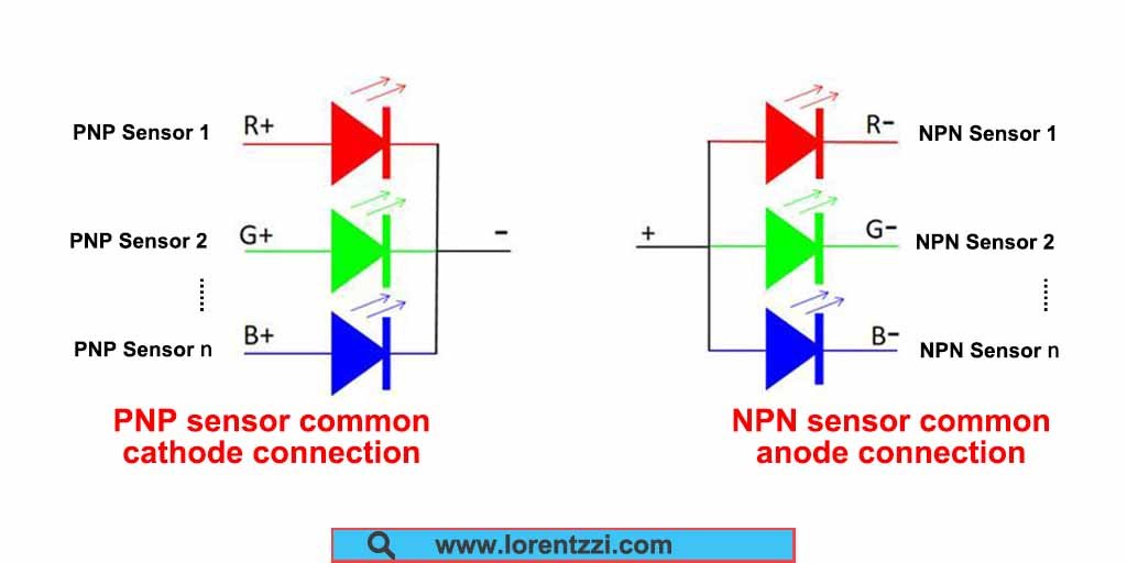
NPN Sensors: NPN sensors are widely used in Asian countries such as China and Japan. They typically control the negative terminal (0V) of the power supply. For example, an NPN normally open (NO) sensor outputs a low-level signal when it detects an object.
PNP Sensors: Unlike NPN sensors, PNP sensors hold the majority of the market share in Europe and the United States. They typically control the positive terminal (VCC) of the power supply. Similarly, a PNP normally open (NO) sensor outputs a high-level signal when it detects an object.
Tips: Want to know more differences between the NPN and PNP sensors, you can read our article: PNP Vs NPN Proximity Sensors: Key Differences, Wiring Diagram And How To Choose.
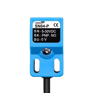
Method 1: Check the nameplate and circuit diagram
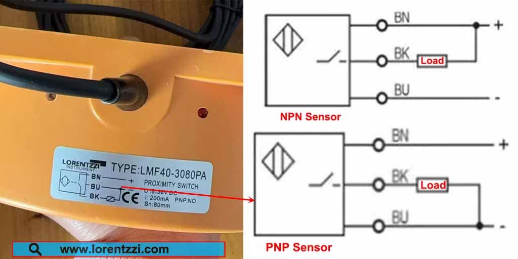
The simplest way to identify whether a sensor is NPN or PNP type is to check its nameplate. The brown wire (BN) needs to be connected to the positive terminal of the power supply, and the blue wire (BU) needs to be connected to the negative terminal. There is no difference between NPN and PNP type sensors in this respect.
The difference lies in their signal wires (BK, black wire).
As shown on the right side of the diagram above, the signal wire of a PNP type sensor needs to be connected to the negative terminal (BU, blue wire) to form a complete closed circuit.
Conversely, the signal wire of an NPN type sensor needs to be connected to the positive terminal to form a complete closed circuit.
Therefore, compared to the wiring diagrams for PNP and NPN type sensors on the right, the sensor on the left side of the diagram is a PNP type output sensor.
Method 2: Multimeter voltage measurement (most recommended)
For electrical engineers or electricians, a multimeter is the most commonly used testing tool. So, can we use it to test the type of a sensor? The answer is yes. Below is a guide on how to use a multimeter to determine whether a sensor is NPN or PNP type.
First, prepare the following materials: an AC RCBO, a 24V DC switching power supply, the sensor under test, and a multimeter.
The operating steps are as follows:

- Connect AC power to the input terminal of the switching power supply through the RCBO(Residual Circuit Breaker with Overload protection) (Note: the RCBO should be in the open state at this time; do not connect power).
- Connect the sensor’s power cord to the switching power supply: connect the brown wire to the positive terminal (+24V) of the switching power supply, and the blue wire to the negative terminal (0V).
- Set the multimeter to the DC voltage range (DCV). Connect the red probe to the positive terminal (+24V) of the switching power supply, and the black probe to the black signal wire (output wire) of the sensor.
- Close the RCBO to supply power to the sensor. Then, bring the object to be measured close to the sensor’s detection surface to activate the sensor, and simultaneously observe the voltage value displayed on the multimeter.
- Judgment Method:
If the multimeter displays approximately 24V (i.e., the power supply voltage), the sensor is an NPN type (because an NPN type outputs a low level, the black wire is conductive to ground, so the voltage between the positive terminal and the black wire is 24V);
If the multimeter displays close to 0V, the sensor is a PNP type (because a PNP type outputs a high level, the black wire is conductive to the positive terminal, so the voltage between the positive terminal and the black wire is 0V).
Note: Ensure correct wiring during operation to avoid short circuits. The sensor must be in working condition during measurement, and safety precautions must be taken.
Method 3: Using a PNP/NPN sensor tester
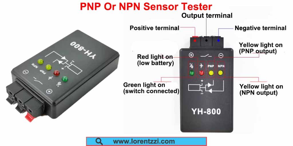
If you have a sufficient budget and frequently need to distinguish sensor types, the sensor tester shown in the image above is a better choice. It’s faster and simpler than using a multimeter.
Below, we’ll explain how to use this sensor tester.
It’s very simple to use. Just connect the brown wire of the sensor to the positive terminal of the tester, the blue wire to the negative terminal, and the sensor signal wire to the output terminal. After wiring, turn on the tester, and it will automatically identify the sensor type: if it’s a PNP type, the yellow PNP indicator light will illuminate; if it’s an NPN type, the NPN indicator light will illuminate.
Conclusion
In short, you can determine whether your sensor is NPN or PNP type by reading the sensor nameplate and wiring diagram, and using a multimeter or PNP/NPN sensor tester.
If you still have questions about sensor differentiation or need technical support, Lorentzzi Electric offers free consultation. You can contact us by emailing shonxu@lorentzzi.com, and our staff will reply within 24 hours.