Both PNP and NPN proximity sensors are widely used in industrial automation, for example, to detect the position of moving objects, replace contact limit switches, detect the speed of rotating objects, count the object’s numbers, etc.
But do you know the difference between them, their wiring diagrams, and how to choose? This article will provide you with a detailed explanation, so let’s start learning now!

What are proximity sensors?
To better understand PNP and NPN sensors, first we need to know what proximity sensors are.
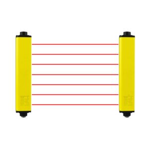
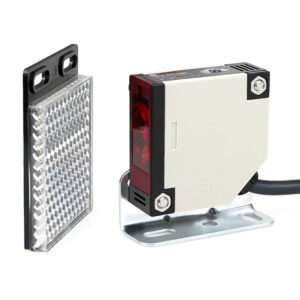
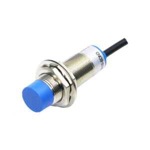
A proximity sensor is a non-contact switch that outputs a specific voltage or current signal when an object enters its detection range. And according to the sensing technologies differences, the proximity sensors can be divided into inductive proximity sensors, capacitive proximity sensors, photo-electronic sensors( safety light curtain ), hall sensors, ultrasonic sensors. The first proximity sensor was invented in 1958 by German engineers Wilfried Gehl, Walter Pepperl, and Ludwig Fuchs. Walter Pepperl and Ludwig Fuchs were also the founders of the German company Pepperl+Fuchs.

Understanding PNP vs. NPN is critical for seamless integration with controllers such as PLCs.
What are PNP proximity sensors?

The PNP proximity sensor, also known as a “sourcing sensor”, works by providing a high voltage to the load when the detected object is within its detection range. This action effectively supplies power to the load, allowing it to operate as intended.
What are NPN proximity sensors?

In contrast, NPN proximity sensors are referred to as “sinking sensors”. Instead of sourcing power to the load, they create a path to ground, allowing current to flow from the load through the sensor to the ground. This means the load must be connected to a positive voltage source, with one end of the load connected to the positive terminal and the other end to the output signal wire of the proximity sensor.
PNP Vs NPN Proximity Sensors: Key Differences
The main differences between PNP and NPN proximity sensors are current, voltage output, PLC compatibility, and regional preference.
The following table lists the detailed comparison:
| Factor | PNP Sensors | NPN Sensors |
|---|---|---|
|
Current flow |
Sensor output->load->ground |
Positive pole -> load -> sensor output |
|
Voltage output |
High-side switching (+24V) |
Low-side switching (0V) |
|
PLC Compatibility |
Matches sinking PLC inputs |
Matches sourcing PLC inputs |
|
Regional preference |
Common in Europe |
Common in Asia |
NPN and PNP sensor wiring diagram

I have a trick for remembering NPN and PNP sensor wiring diagrams in an easier way. You can see the letters “NPN”. The first two letters “NP” can cancel each other out, leaving only one letter “N”, so the output of the NPN sensor is a Negative signal. So when powering the load, you need to provide a positive terminal to form a loop with the output of the NPN sensor.
On the contrary, the first two letters of the PNP sensor cancel each other out, leaving only a letter “P”, so the output of the PNP sensor is Positive and the other end of the load needs to be connected to 0V to form a loop to control the load.
My trick may not be very scientific, but I hope it helps you remember wiring diagrams a little easier.
PNP and NPN proximity sensor selection guide
When choosing a PNP or NPN proximity sensor, there are several factors to consider:
- Check your PLC type: Most proximity sensors need to be used with a programmable logic controller (PLC) to achieve specific control purposes. If your PLC input cards only support NPN transistor inputs, you should use an NPN proximity sensor. Conversely, if your PLC input cards only support PNP transistor inputs, you should opt for a PNP proximity sensor. Using the wrong type of proximity sensor may cause the PLC to not function properly.
- Wiring consideration: NPN systems usually share a common ground connection. PNP systems usually share a common positive connection. In large systems, maintaining a consistent wiring approach (all PNP or all NPN) can simplify installation. Therefore, if your system is designed with PNP wiring, try to use a PNP sensor, and if it is an NPN system, use an NPN sensor.
- Noise Immunity: NPN Sensors: Generally have better noise immunity in electrically noisy environments. PNP Sensors: May be more susceptible to electrical interference in certain applications.
- Cost consideration: Cost considerations: The prices of these two types of proximity sensors are basically the same, but due to the supplier’s inventory, the price of one type of sensor may be slightly cheaper. As one of the Chinese sensor suppliers, Lorentzzi‘s prices for PNP sensors and NPN sensors will not differ due to inventory differences. We have always been committed to providing customers with cost-effective sensor products.
Conclusion
In general, a PNP proximity sensor outputs a high-level signal when it detects a target and provides positive power to the load, so it is often called a source sensor; while an NPN proximity sensor outputs a low-level signal when it detects a target and connects the load to the ground, so the other end of the load needs to be connected to the positive pole of the power supply.
If you have additional questions or need a quote for your NPN or PNP sensor needs, please email us at shonxu@lorentzzi.com for support!