In the wave of digitalization and automation, incremental rotary encoders play a pivotal role. This article will delve into the principles, types, and real-life application scenarios of incremental encoders to help you better understand this important technology.
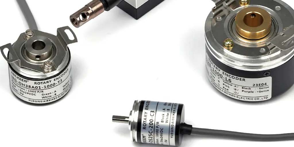
Table of Contents
What is an incremental rotary encoder?
Incremental rotary encoders are sensors that can convert the rotational speed, direction of movement, and displacement of rotating or linear moving objects into pulse signals that can be transmitted and stored.
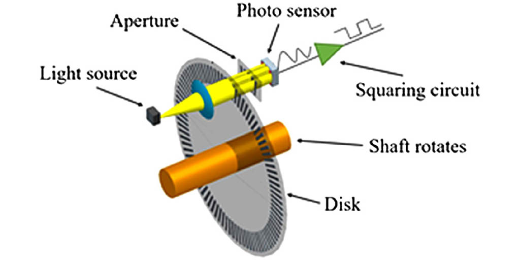
Incremental rotary encoder working principle
The incremental encoder working principle is to count the received signal of the optical or magnetic detection head according to the stripes or gaps on the disk, thereby measuring the distance and direction of rotation or displacement. When the encoder disk rotates, the optical detection head will generate pulse signals as the stripes or gaps move. Each pulse represents a certain angle of rotation of the encoder disk. Incremental encoders generally have two output signals, namely A-phase and B-phase signals. By counting the A-phase and B-phase signals and measuring the phase difference, the rotation angle or linear displacement distance of the measured object can be calculated.
Incremental rotary encoders types
According to the working principle differences, there are 3 types of incremental rotary encoders, they are magnetic, optical and mechanical encoder. Here below the descriptions of each type of them:
Incremental magnetic rotary encoder
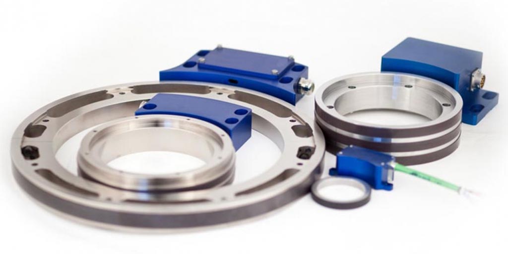
Magnetic incremental encoder: Magnetic incremental encoder uses magnetic lines of force to generate pulse signals. On the rotating encoder wheel, the alternating changes in the magnetic field lines are detected and converted into pulse signals.
Compared with traditional incremental optical encoders, incremental magnetic encoders do not require a code disk and a light source, have fewer components, and have a simpler detection structure; at the same time, the hall element itself also has many advantages, such as: solid structure, Small size, light weight, long life, vibration resistance, and not afraid of pollution or corrosion from dust, oil, water vapor, salt spray, etc.
Incremental optical rotary encoder
Optical incremental encoder: This encoder uses optical principles to generate pulse signals. Light passes through a grating on a rotating encoder wheel, creating alternating light and dark areas, thereby generating a pulse signal.
Incremental mechanical rotary encoder
Mechanical incremental encoder: Mechanical incremental encoder uses mechanical contact to generate pulse signals. When the encoder body rotates, the contact points slide on the metal conductive sheet, thereby generating a pulse signal.
Incremental rotary encoder arduino code
An ABZ incremental rotary encoder provides three channels: A, B, and Z (also known as the index channel). The A and B channels are used for determining position and direction, just like in a standard AB encoder. The Z channel provides a single pulse per revolution and is often used for a “home” or “zero” position.
Here’s a simple Arduino code snippet for reading an ABZ incremental rotary encoder:
// Define encoder pin connections & initial values
const int encoderPinA = 2;
// Connected to A channel pin on encoder
const int encoderPinB = 3;
// Connected to B channel pin on encoder
const int encoderPinZ = 4; // Connected to Z channel pin on encoder (Index)
volatile int encoderPos = 0; // Position counter
int lastReportedPos = 0; // Last reported position
int aState;
int aLastState;
void setup() {
// Setup Serial Monitor
Serial.begin(9600);
// Configure encoder pins as inputs
pinMode(encoderPinA, INPUT_PULLUP);
pinMode(encoderPinB, INPUT_PULLUP);
pinMode(encoderPinZ, INPUT_PULLUP);
// Read the initial state of encoderPinA
aLastState = digitalRead(encoderPinA);
// Attach interrupts
attachInterrupt(digitalPinToInterrupt(encoderPinA), readEncoder, CHANGE);
attachInterrupt(digitalPinToInterrupt(encoderPinZ), resetEncoder, RISING);
}
void loop() {
// Check if position has changed since last reported
if (lastReportedPos != encoderPos) {
Serial.print(“Position: “);
Serial.println(encoderPos);
lastReportedPos = encoderPos;
}
}
// Interrupt function for reading encoder A and B channels
void readEncoder() {
aState = digitalRead(encoderPinA); // Reads the “current” state of the encoderPinA
// If the previous and the current state of the encoderPinA are different, that means a Pulse has occurred
if (aState != aLastState) {
// If the B channel state is different to the A channel state, that means the encoder is rotating clockwise
if (digitalRead(encoderPinB) != aState) {
encoderPos++;
} else {
encoderPos–;
}
Serial.print(“Position = “);
Serial.println(encoderPos);
}
aLastState = aState; // Updates the previous state of the encoder with the current state
}
// Interrupt function for reading encoder Z channel (Index)
void resetEncoder() {
encoderPos = 0; // Reset the encoder position to zero
Serial.println(“Index detected, position reset to zero”);
}
How to use this Arduino code
- Connect the A, B, and Z channels of your ABZ incremental rotary encoder to pins 2, 3, and 4 on your Arduino, respectively.
- Upload the code to your Arduino.
- Open the Serial Monitor to view the encoder position and index resets
Incremental vs absolute rotary encoder
There are 14 differences between an incremental and absolute rotary encoder, the below tables will show all the differences between them:
Applications of incremental encoders
Automated production lines: In automated production lines, incremental encoders are used to measure and control the position of machines. For example, on an assembly line, encoders can precisely control the position of components to ensure correct assembly.
Robotics: Incremental encoders play an important role in robotics, providing accurate motion feedback so that robots can precisely control their own movements.
Servo Motor Control: Servo motors require precise position feedback for precise control. Incremental encoders are a key component in providing this feedback,
Conclusion
Incremental encoders are an important part of modern industrial and automation applications. By in-depth understanding of the principles, types and applications of incremental encoders, we can better understand their important role in various industrial automation scenarios. Although there are some challenges, with the continuous advancement of technology, we have reason to believe that incremental encoders will play a greater role in the future and promote progress in the field of industrial automation. Hopefully this article has helped you gain a deeper understanding of incremental encoders and piqued your interest in this important technology.