Solid state relays can be classified as single phase DC AC solid state relays, single phase AC AC solid state relays, three phase DC AC solid state relays, three phase AC AC solid state relays, and DC DC solid state relays.
Different solid state relays have different wiring diagrams.
So now let’s have a look at their wiring diagrams.
Single phase DC AC solid state relays wiring:
The control voltage of this solid-state relay is 3-32 VDC.
By referring to the wiring diagram on the solid-state relay label, we can see that terminal 3 is the positive pole of the control signal, marked with “+”, and terminal 4 is the negative pole of the control signal, marked with “-“.
Now we need to find a power supply that can generate a voltage between 3-32 VDC. For example, we can use a Meanwell MDR-10-24 switching power supply as a control device, it can output 24 VDC voltage.
When wiring, be sure to connect positive pole to positive terminal, negative pole to negative terminal.
On the load side, the AC power and the load need to be connected in series.
It is important to note that for resistive loads, their power needs to be less than or equal to half of the SSR maximum output power.
The power of inductive loads needs to be less than one seventh of the maximum output power of the solid-state relay(why so? see this article).
Its wiring diagram is as follows:

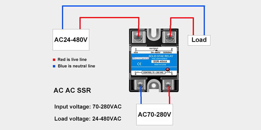
Single phase AC AC solid state relays wiring:
Unlike DC-AC solid-state relays, AC-AC solid-state relays have a control signal of 70-280VAC and a load side of 24-480VAC. The wiring of this type of solid-state relay is very simple.
We can connect the AC voltage to both control side and the load side.
Since AC power does not have positive or negative poles, the phase line and the neutral line can be connected to the control and load terminals as desired.
The wiring diagram is as follows:
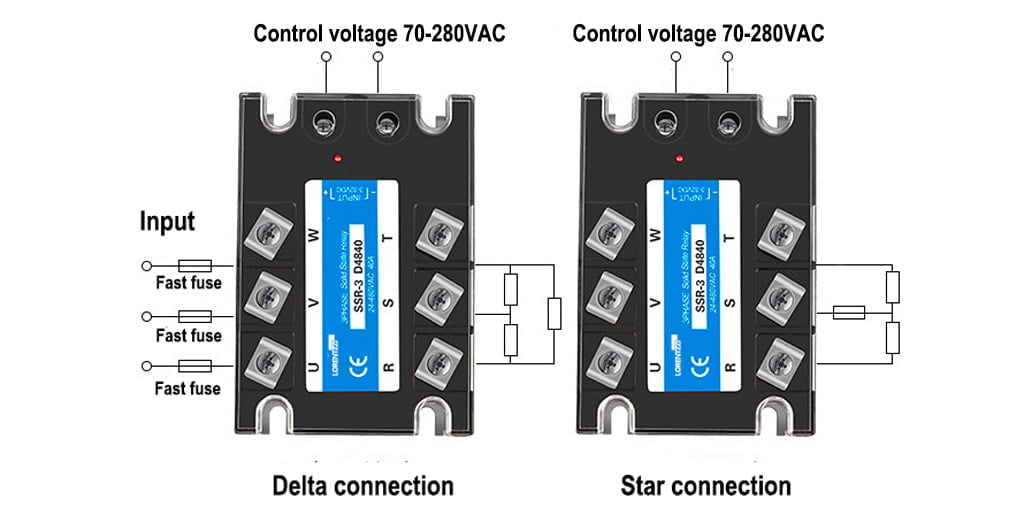
Three phase DC AC solid state relay wiring:
The 3 phase DC AC solid state relay wiring diagram is nearly same as the single phase one.
The only difference lies in 380 VAC or 220 VAC 3 phase load voltage.
The connection between three-phase power and the load can be either star or delta.
The delta connection will produce much more power than the star connection and can drive larger loads.
We shall take the maximum load capacity and SSR maximum output power into consideration, the maximum resistive load power that a three-phase solid-state relays can drive is (current*load voltage*1.732)÷2, and the maximum inductive load power is (current*load voltage*1.732)÷7.
The wiring diagram is as follows:

3 phase AC AC solid state relays wiring:
The control voltage for three-phase AC-AC solid-state relays is 70-280VAC, and the load side voltage range is 24 to 480VAC.
We can lead out any phase of the load side and connect it with the neutral line to the control terminal to control the on/off of the three-phase load side.
The wiring diagram is as follows:
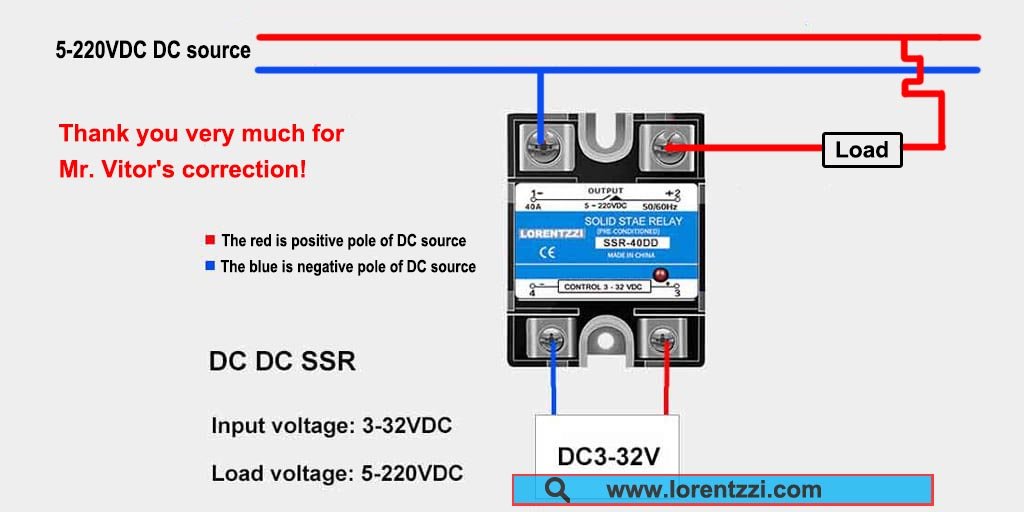
Wiring instructions for DC-DC solid-state relays:
DC-DC solid-state relays control 24-220VDC switches with a control voltage of 3-32VDC.
When the input of 3-32VDC is connected, the load side will also be connected accordingly. This achieves control of high voltage and large current with low voltage and low current.
The wiring diagram is as shown below.
It is important to note that if the load current of any solid-state relay is greater than 10 A, it needs to be used with a heat sink.
Frequent switching or continuous operation can generate a large amount of heat in the solid-state relay.
If this heat is not dissipated in time, it can cause permanent damage to the solid-state relay.
Conclusion
Different SSR wiring diagrams are completely different. I think through the above learning, we can clearly know how to connect the solid-state relay.
If you still have problems with SSR wiring, please feel free to contact us or send an email to shonxu@lorentzzi.com, we will provide free help.