Purchasing a good quality solid state relay is one thing, but how to test a solid state relay is a same vital matter. Solid state relay is a kind of electronic switch, which has the characteristics of fast response and high reliability, and is widely used in industrial control, automation equipment and other fields. However, during use, the solid state relay will also be damaged. How to quickly and accurately detect the quality of the solid state relay is very important. This article will introduce 3 measurement methods and precautions of solid state relays to help you perform practical operations.
1. Measurement method
Using DC resistance measurement method to test a solid state relay
The DC resistance measurement method is a simple and effective method for measuring solid state relays. First, put the multimeter in the resistance position, and connect the red and black test leads to the input and output terminals of the solid state relay respectively. If the solid state relay is normal, the resistance value displayed by the multimeter should be close to 0 ohms; if the resistance value exceeds several thousand ohms or is infinite, then the solid state relay has been damaged.

Using AC voltage measurement method to test a solid state relay
AC voltage measurement is a commonly used measurement method for solid state relays. First, connect the input terminal and output terminal of the solid state relay to an AC power source and a load respectively. After turning on the power switch, if the solid state relay is normal, the AC voltage should be accurately delivered to the load, and the working status of the load should be the same as that of no use. The same is true for solid state relays; if the solid state relay is damaged, the AC voltage cannot be delivered to the load, the load will not work properly, or there will be a significant voltage drop.
Using Pulse signal measurement method to test a solid state relay
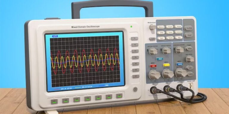
Pulse signal measurement can help measure the switching speed and response time of solid state relays. First, connect the pulse signal source to the input terminal of the solid state relay, and connect the probe of the oscilloscope to the output terminal of the solid state relay. When the pulse signal source outputs a pulse signal, if the solid state relay is normal, a clean pulse should appear on the oscilloscope The waveform, the rise time and fall time of the waveform should be very short; if the waveform is fuzzy, distorted, or the response time is too long, then the solid state relay has been damaged.

2. Matters needing attention
- When measuring solid state relays, the power supply should be disconnected first to ensure safe operation.
- When measuring DC resistance, disconnect the input terminal and output terminal of the solid state relay, and confirm that the solid state relay has been completely powered off, otherwise the multimeter may be damaged.
- When performing AC voltage measurement and pulse signal measurement, the appropriate power supply and load should be selected according to the rated voltage and rated current of the solid state relay, and ensure that the test conditions meet the working requirements of the solid state relay.
- When measuring pulse signals, you should choose a suitable oscilloscope probe to ensure the accuracy and stability of the test signal.
- When measuring the solid state relay, you should pay attention to observe the reaction of the solid state relay, and combine other measurement data to judge whether the solid state relay is good or bad.
Conclusion
In summary, solid state relays are an important electronic component that are widely used in industrial control and automation equipment. The correct use of the measurement method of the solid state relay can help to detect the quality of the solid state relay and improve the reliability and stability of the equipment. However, when measuring solid-state relays, you need to pay attention to safety matters and operating points to ensure the accuracy and reliability of the measurement results.


