The float switch is a structurally simple component used for liquid level control. It does not have complex circuits and is not susceptible to interference.
As long as the correct material is chosen, it can be used with any type of liquid, pressure, or temperature, making it widely applicable in water treatment equipment and other fields.
But how does the liquid level sensor control the water level? What is its control principle? And how does it control the water pump for supply and drainage?
Let me explain in detail.
Float switch working principle
First, let’s talk about the working principle of the float switch.
The tank level switch operates using magnetism.
As the float inside the float rises or falls with the liquid level, it causes the reed switch chip at the set position in the detection tube to actuate, generating a contact switch or conversion signal.
Inside a sealed non-magnetic tube, one or more reed switches are installed. This tube is passed through one or more hollow float balls with a ring-shaped magnet inside.
The rise or fall of the liquid will cause the float ball to move up and down, thereby causing the reed switch in the non-magnetic tube to attract or disconnect, resulting in an output switch signal.
This may be a bit difficult to understand, so let me explain it in a simpler way. This liquid switch consists of a float and a weight.
The weight serves to fix the position, allowing the float to float in a specific area. Inside the float, there is a steel ball. When the float rises or falls, the steel ball rolls and pushes the lever, which in turn activates the micro-switch.
The micro-switch has three wires, namely the common terminal, normally open, and normally closed.
These normally open and normally closed terminals are the switch signals mentioned earlier.

How to identify each cable of a float switch?
As mentioned earlier, the float switch has three wires: the common terminal, normally open, and normally closed.
Before wiring, we need to determine the function of these three wires.
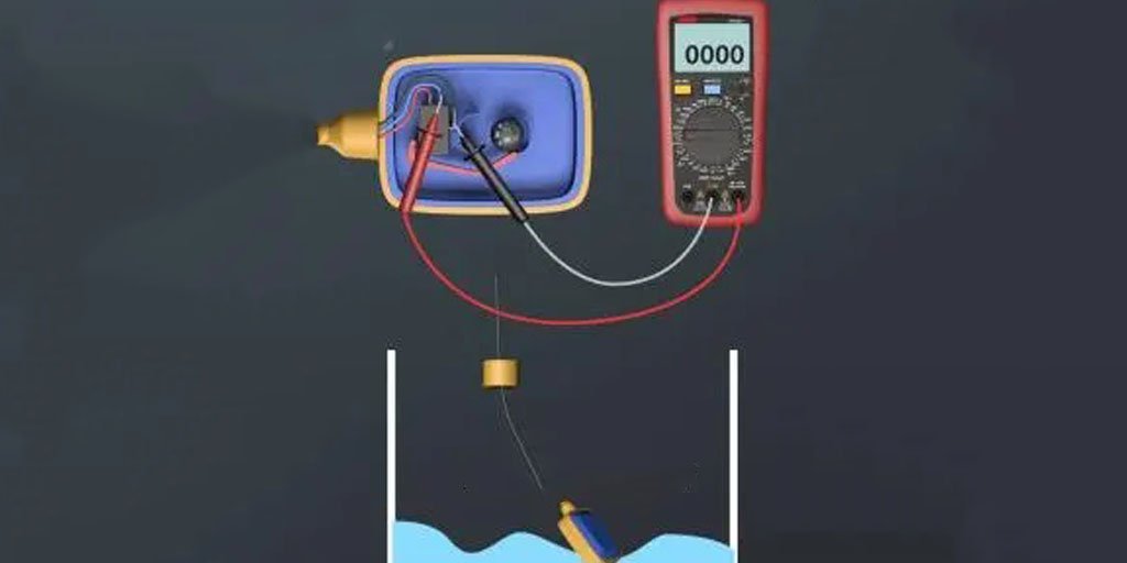
For water supply, it is low start and high stop, while for drainage, it is high start and low stop. Knowing this principle, we can use a multi-meter to measure.
For water supply, with the Liquid level sensor at a low liquid level, we can set the multi-meter to the buzzer mode and test the continuity of any two wires.
If we find that the black and blue wires are connected, based on the low start and high stop principle, we connect the water supply to the black and blue wires, and do not connect the brown wire.
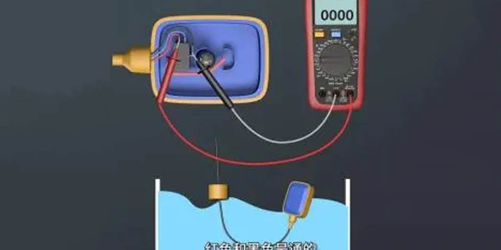
For drainage, with the float switch at a high liquid level, we can test the continuity again.
If we find that the brown and black wires are connected, based on the high start and low stop principle, we connect the drainage to the black and brown wires, and do not connect the blue wire.
After measuring the function of the three wires of the float level sensor and determining how to wire for supply and drainage, prepare a ground fault circuit interrupter (GFCI), an AC contactor, a float level sensor, and a water pump motor.
Now we can proceed with the actual wiring.
Float switch applications
The float switch is mainly used for liquid level control, such as controlling the water pump for supply and drainage.
When it comes to the use and wiring of the float switch, it is important to note that this product only serves as a signal and cannot directly control the water pump.
An accessory for signal collection, such as an intermediate relay or an AC contactor, must be added in between.
Let’s take a look at the wiring for controlling the water pump for supply and drainage using a float switch.
Wiring of a float switch for water supply and drainage
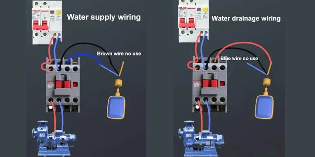
For water supply: Connect the neutral and live wires of the GFCI to the input terminals of the main contacts of the contactor.
Connect the output terminals of the main contacts of the contactor to the water pump motor.
Connect coil A1 to the live wire and coil A2 to the blue wire of the float type sensor.
Connect the black wire back to the neutral wire, and do not connect the brown wire.
For drainage: Connect the neutral and live wires of the GFCI to the input terminals of the main contacts of the contactor.
Connect the output terminals of the main contacts of the contactor to the water pump motor.
Connect coil A1 to the live wire and coil A2 to the brown wire of the float switch.
Connect the black wire back to the neutral wire, and do not connect the blue wire.
Conclusion
So, we’ve covered the working principle of the float switch, how it controls the water level, and finally, the measurement and wiring for controlling the water pump for supply and drainage using this switch.
Have you learned something?
If you have any further questions, please feel free to email shonxu@lorentzzi.com.