Поплавковый выключатель - это конструктивно простой компонент, используемый для контроля уровня жидкости. Он не имеет сложных схем и не восприимчив к помехам.
При условии правильного выбора материала он может использоваться с любым типом жидкости, давлением или температурой, что делает его широко применимым в оборудовании для очистки воды и других областях.
Но как датчик уровня жидкости контролирует уровень воды? Каков принцип его управления? И как он управляет водяным насосом для подачи и отвода воды?
Позвольте мне объяснить подробнее.
Принцип работы поплавкового выключателя
Прежде всего, давайте поговорим о принципе работы поплавкового выключателя.
Переключатель уровня воды в баке работает на магнетизме.
Когда поплавок внутри поплавка поднимается или опускается вместе с уровнем жидкости, это приводит к срабатыванию герконового переключателя в заданном положении в трубке обнаружения, генерируя контактный переключатель или сигнал преобразования.
Внутри герметичной немагнитной трубки установлены один или несколько герконов. Через эту трубку проходит один или несколько полых шариков-поплавков с кольцеобразным магнитом внутри.
Подъем или опускание жидкости заставляет шарик поплавка двигаться вверх и вниз, тем самым заставляя геркон в немагнитной трубке притягиваться или отсоединяться, что приводит к выходному сигналу переключателя.
Это может быть немного сложно для понимания, поэтому позвольте мне объяснить это более простым способом. Этот жидкостный переключатель состоит из поплавка и грузика.
Грузило служит для фиксации положения, позволяя поплавку плавать в определенной зоне. Внутри поплавка находится стальной шарик. Когда поплавок поднимается или опускается, стальной шарик катится и толкает рычаг, который, в свою очередь, активирует микровыключатель.
Микропереключатель имеет три провода: общий, нормально разомкнутый и нормально замкнутый.
Эти нормально разомкнутые и нормально замкнутые клеммы являются сигналами переключателя, о которых говорилось ранее.

Как определить каждый кабель поплавкового выключателя?
Как уже упоминалось, поплавковый выключатель имеет три провода: общий, нормально открытый и нормально закрытый.
Перед подключением необходимо определить назначение этих трех проводов.
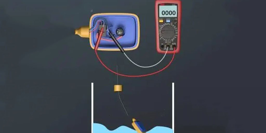
Для водоснабжения это низкий старт и высокий стоп, а для водоотведения - высокий старт и низкий стоп. Зная этот принцип, мы можем использовать мультиметр для измерения.
Для водоснабжения, с Датчик уровня жидкости при низком уровне жидкости, мы можем перевести мультиметр в режим зуммера и проверить целостность любых двух проводов.
Если мы обнаружим, что черный и синий провода соединены, то, исходя из принципа "низкий старт и высокий стоп", мы подключаем подачу воды к черному и синему проводам, а коричневый провод не подключаем.
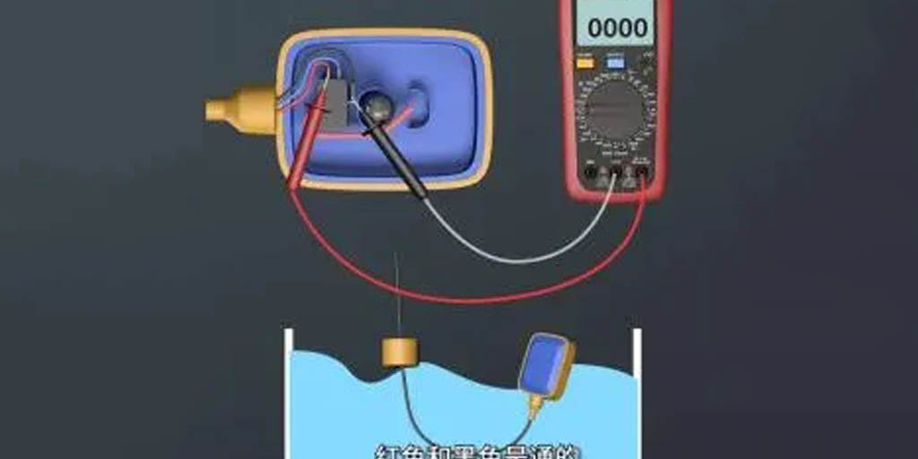
При сливе, когда поплавковый выключатель находится на высоком уровне жидкости, мы можем снова проверить целостность.
Если мы обнаружим, что коричневый и черный провода соединены, то, исходя из принципа "высокий старт - низкий стоп", подключаем дренаж к черному и коричневому проводам, а синий провод не подключаем.
Измерив функции трех проводов поплавкового датчика уровня и определив, как подключить питание и слив, подготовьте прерыватель цепи замыкания на землю (GFCI), а также Контактор переменного тока, датчик уровня поплавка и двигатель водяного насоса.
Теперь мы можем приступить к прокладке проводов.
Применение поплавковых выключателей
Поплавковый выключатель в основном используется для контроля уровня жидкости, например, для управления водяным насосом для подачи и отвода воды.
Когда речь заходит об использовании и подключении поплавкового выключателя, важно отметить, что это изделие служит только для подачи сигнала и не может напрямую управлять водяным насосом.
Между ними необходимо установить дополнительное устройство для сбора сигнала, например, промежуточное реле или контактор переменного тока.
Давайте рассмотрим схему управления водяным насосом для подачи и слива воды с помощью поплавкового выключателя.
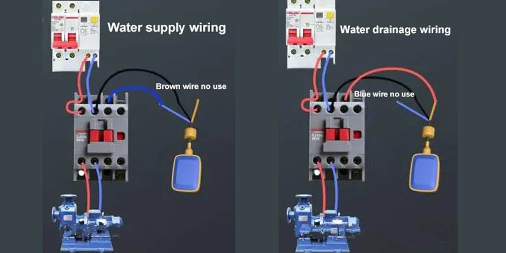
Подключение поплавкового выключателя для водоснабжения и водоотведения
Для водоснабжения: Подключите нейтральный и токоведущий провода GFCI к входным клеммам главных контактов контактора.
Подключите выходные клеммы главных контактов контактора к двигателю водяного насоса.
Подключите катушку A1 к проводу под напряжением, а катушку A2 - к синему проводу датчика поплавкового типа.
Подключите черный провод обратно к нейтральному проводу, а коричневый провод не подключайте.
Для дренажа: Подключите нейтральный и токоведущий провода GFCI к входным клеммам главных контактов контактора.
Подключите выходные клеммы главных контактов контактора к двигателю водяного насоса.
Подключите катушку A1 к проводу под напряжением, а катушку A2 - к коричневому проводу поплавкового выключателя.
Подключите черный провод обратно к нейтральному проводу, а синий провод не подключайте.
Заключение
Итак, мы рассмотрели принцип работы поплавкового выключателя, то, как он контролирует уровень воды, и, наконец, измерения и проводку для управления водяным насосом для подачи и слива воды с помощью этого выключателя.
Вы чему-то научились?
Если у вас возникнут дополнительные вопросы, пожалуйста, пишите по электронной почте shonxu@lorentzzi.com.