


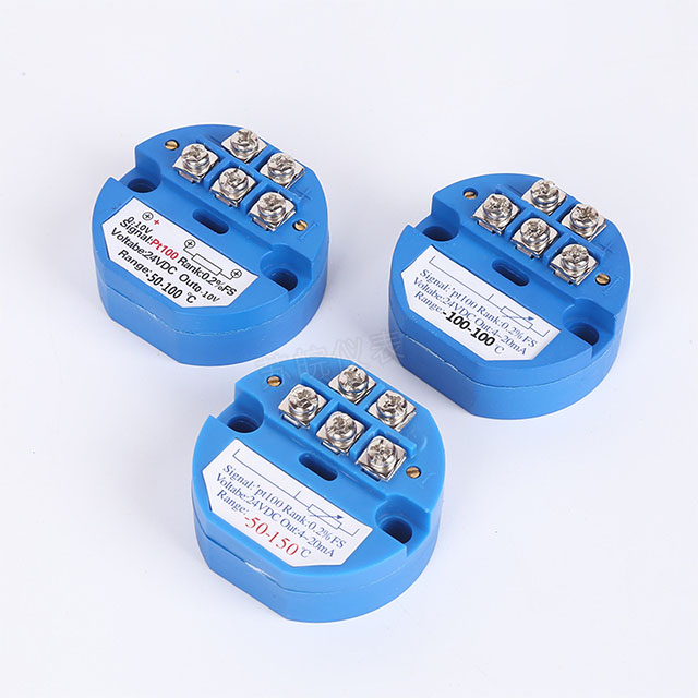
Os transmissores de temperatura são componentes muito importantes e comuns em sistemas. Mas o que é um transmissor de temperatura, como ele funciona, por que devemos usá-lo, etc.? Este artigo fornecerá todas as informações que você deseja saber. Vamos começar agora! Índice O que é um transmissor de temperatura? Temperatura
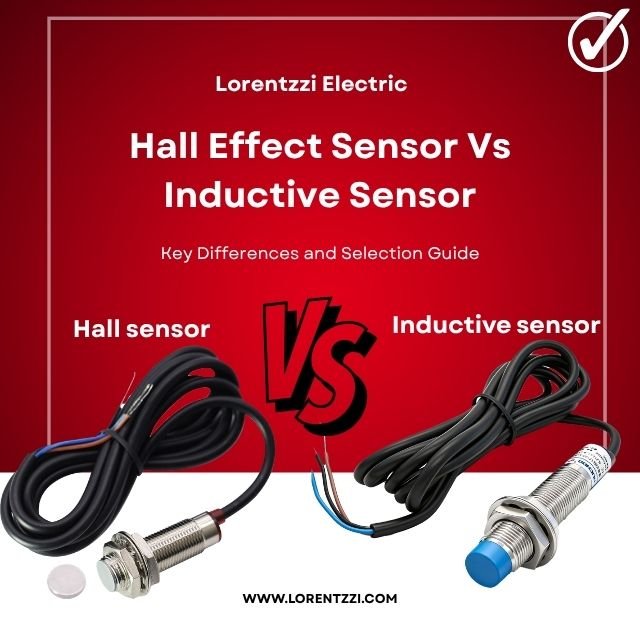
Os sensores de proximidade indutivos podem detectar objetos metálicos, mas identificar diferentes tipos de objetos metálicos é outra questão. Vamos dar uma olhada em como distinguir entre objetos metálicos e magnéticos. A resposta e a solução são simples: você pode usar o sensor de proximidade indutivo para detectar objetos metálicos, enquanto pode usar o sensor de proximidade magnético para detectar objetos magnéticos.

Você já observou uma linha de montagem automatizada, com dezenas de motores, sensores e atuadores movendo-se em sequência perfeita sem um único erro? O que mantém todos eles em sintonia? Não por acaso, mas por um condutor oculto. Muitas pessoas pensam que os microprocessadores ou microchips são os verdadeiros controladores, mas o