El interruptor de flotador es un componente estructuralmente sencillo que se utiliza para controlar el nivel de líquido. No tiene circuitos complejos y no es susceptible a interferencias.
Siempre que se elija el material correcto, puede utilizarse con cualquier tipo de líquido, presión o temperatura, por lo que es ampliamente aplicable en equipos de tratamiento de aguas y otros campos.
Pero, ¿cómo controla el nivel de agua el sensor de nivel de líquido? ¿Cuál es su principio de control? ¿Y cómo controla la bomba de agua para el suministro y el drenaje?
Se lo explicaré con detalle.
Principio de funcionamiento del interruptor de flotador
En primer lugar, hablemos del principio de funcionamiento del interruptor de flotador.
El interruptor de nivel del depósito funciona por magnetismo.
A medida que el flotador del interior sube o baja con el nivel del líquido, hace que el chip del interruptor de láminas situado en la posición fijada en el tubo de detección se accione, generando un interruptor de contacto o una señal de conversión.
En el interior de un tubo sellado no magnético se instalan uno o varios interruptores de láminas. Este tubo se hace pasar por una o varias bolas flotantes huecas con un imán en forma de anillo en su interior.
La subida o bajada del líquido hará que la bola del flotador se mueva hacia arriba y hacia abajo, provocando así que el interruptor de láminas del tubo no magnético se atraiga o se desconecte, dando lugar a una señal de conmutación de salida.
Esto puede ser un poco difícil de entender, así que permítanme explicarlo de una manera más sencilla. Este interruptor de líquido consta de un flotador y un peso.
El peso sirve para fijar la posición, permitiendo que el flotador flote en una zona determinada. Dentro del flotador hay una bola de acero. Cuando el flotador sube o baja, la bola de acero rueda y empuja la palanca, que a su vez activa el microinterruptor.
El microinterruptor tiene tres hilos: el terminal común, el normalmente abierto y el normalmente cerrado.
Estos terminales normalmente abiertos y normalmente cerrados son las señales de conmutación mencionadas anteriormente.

¿Cómo identificar cada cable de un interruptor de flotador?
Como ya se ha mencionado, el interruptor de flotador tiene tres cables: el terminal común, el normalmente abierto y el normalmente cerrado.
Antes de proceder al cableado, debemos determinar la función de estos tres hilos.
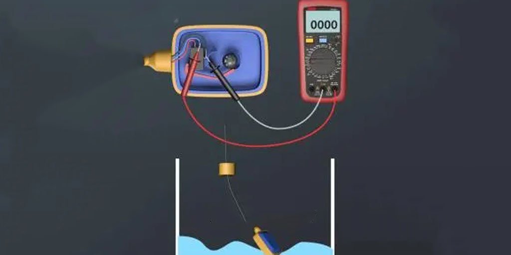
Para el suministro de agua, es arranque bajo y parada alta, mientras que para el drenaje, es arranque alto y parada baja. Conociendo este principio, podemos utilizar un multímetro para medir.
Para el suministro de agua, con la Sensor de nivel de líquido en un nivel de líquido bajo, podemos poner el multímetro en modo zumbador y comprobar la continuidad de dos cables cualesquiera.
Si vemos que los cables negro y azul están conectados, basándonos en el principio de arranque bajo y parada alta, conectamos el suministro de agua a los cables negro y azul, y no conectamos el cable marrón.
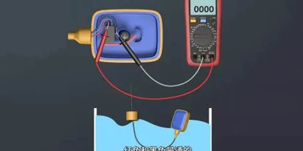
Para el drenaje, con el interruptor de flotador en un alto nivel de líquido, podemos probar la continuidad de nuevo.
Si vemos que los cables marrón y negro están conectados, basándonos en el principio de arranque alto y parada bajo, conectamos el drenaje a los cables negro y marrón, y no conectamos el cable azul.
Después de medir la función de los tres cables del sensor de nivel de flotador y determinar cómo cablear para el suministro y el drenaje, prepare un interruptor de circuito de fallo a tierra (GFCI), un Contactor de CAun sensor de nivel de flotador y un motor de bomba de agua.
Ahora podemos proceder al cableado propiamente dicho.
Aplicaciones del interruptor de flotador
El interruptor de flotador se utiliza principalmente para el control del nivel de líquido, como el control de la bomba de agua para el suministro y el drenaje.
En lo que respecta al uso y cableado del interruptor de flotador, es importante tener en cuenta que este producto sólo sirve como señal y no puede controlar directamente la bomba de agua.
En medio debe añadirse un accesorio para la captación de señales, como un relé intermedio o un contactor de CA.
Veamos el cableado para controlar la bomba de agua para suministro y drenaje mediante un interruptor de flotador.
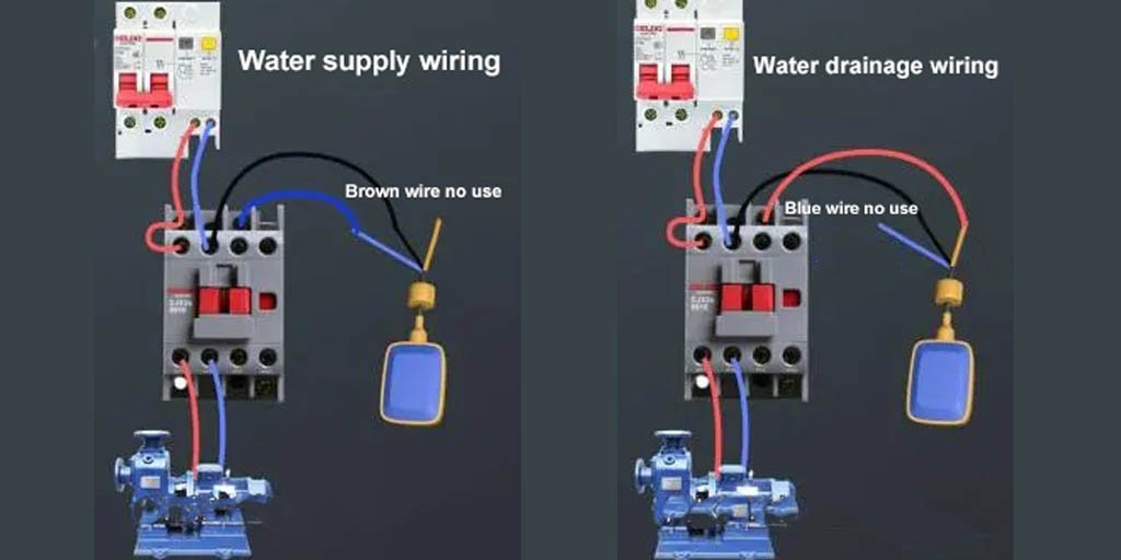
Cableado de un interruptor de flotador para suministro y drenaje de agua
Para el suministro de agua: Conecte los cables neutro y vivo del GFCI a los terminales de entrada de los contactos principales del contactor.
Conecte los terminales de salida de los contactos principales del contactor al motor de la bomba de agua.
Conecte la bobina A1 al cable con corriente y la bobina A2 al cable azul del sensor tipo flotador.
Conecte de nuevo el cable negro al cable neutro y no conecte el cable marrón.
Para drenaje: Conecte los cables neutro y vivo del GFCI a los terminales de entrada de los contactos principales del contactor.
Conecte los terminales de salida de los contactos principales del contactor al motor de la bomba de agua.
Conecte la bobina A1 al cable con corriente y la bobina A2 al cable marrón del interruptor de flotador.
Conecte de nuevo el cable negro al cable neutro y no conecte el cable azul.
Conclusión
Así pues, hemos tratado el principio de funcionamiento del interruptor de flotador, cómo controla el nivel del agua y, por último, la medición y el cableado para controlar la bomba de agua de suministro y drenaje mediante este interruptor.
¿Has aprendido algo?
Si tiene más preguntas, no dude en enviar un correo electrónico a shonxu@lorentzzi.com.